
















The two standards cover the same physical object — the permanent fixed ladder — but have expressly disjoint fields of application. UNI EN ISO 14122-4:2016 (point 1) applies to fixed ladders that are part of a fixed machine, and to the same means of access when it is part of the building or civil structure, provided its main function is to allow access to the machine. UNI 11962:2024 (point 1) applies to permanent fixed ladders with an inclination greater than 75°, fixed to a support, used as a means of access to buildings, infrastructure, structures, works and plants, and expressly states that it does not apply to the fixed ladders covered by UNI EN ISO 14122-4.
The first design step is therefore not dimensional but one of qualification: what the ladder’s main purpose is. Where it is located does not matter — a ladder on a roof may serve a machine, a ladder inside a plant may serve a building landing. The two standards are mutually exclusive: they must not be applied cumulatively.
A useful clarification. UNI 11962 is built on top of 14122-4, not against it: the Introduction states that “UNI EN ISO 14122-4 contains useful references that underpin this standard”, and for most requirements (rungs, loads, tests, stability checks) 11962 refers back to it verbatim. It is therefore best to reason in terms of the differences, not a full comparison.
Table 1 — Where the two standards diverge
| Aspect | UNI EN ISO 14122-4:2016 | UNI 11962:2024 | Design consequence |
| Definition of a fixed ladder (inclination) | 75° < angle of inclination ≤ 90° (UNI EN ISO 14122-1:2016, point 3.1, figure 1). Part 4 does not redefine the inclination: it refers back to Part 1. | Inclination greater than 75° (point 1). | No substantive difference: the 75° threshold is the same in both standards. |
| Requirement for fall protection | Mandatory if the total fall height is > 3,000 mm (point 4.2.1). Below this, the ladder may be without it. | Always present: fall protection is a constituent element of the very definition of “permanent fixed ladder” (point 3.15), and the classification in point 4 does not provide for a “without protection” class. | A 2.5 m ladder with no cage and no line is admissible in a machine context, but not under UNI 11962. Watch the title of UNI 11962: “with or without cage” means class S1, not “without protection”. |
| Type of protection and selection criterion | Two alternatives with an explicit hierarchy: the cage is the preferred choice because it is always present and independent of operator behaviour; the guided fall arrester is only effective if the user chooses to use it. The combination of cage + fall arrester is prohibited (point 4.2.2). | Two alternative classes with no declared hierarchy: S1 (guided-type fall-arrest device on a rigid anchor line, UNI EN 353-1) and S2 (safety cage) — point 4. The choice is made using tables A.1 and A.2 of Appendix A (normative). | In a machine context, the starting point is the cage, moving to the fall arrester only if the cage is not practicable. Outside a machine context, the choice is governed by h and H via tables A.1/A.2, which in practice greatly restrict the use of the cage. |
| Maximum rung length h with cage | h ≤ 6,000 mm for staggered flights (points 4.3.2 and 4.3.3). | h ≤ 5 m: class S2 is not permitted for h > 5 m (table A.1). | A 6 m flight with a cage: compliant with 14122-4, not compliant with 11962. |
| Maximum total height H with cage | No upper limit is specified. For H > 10,000 mm, staggered flights with a cage are permitted and, for untrained users, are the only ones permitted (point 4.3.3; the rule is not repeated in point 4.3.2, i.e. for 3,000 < H ≤ 10,000 mm). | H ≤ 20 m: “ladders fitted with a safety cage may be used up to a height H of 20 m” (point A.3); beyond this, class S2 is not permitted (table A.2). | Beyond 20 m, 11962 effectively requires class S1, and with it trained users, PPE and a rescue procedure. This is the constraint that most often changes the design. |
| Very low heights (H < 2.0 m) | No specific provision: below 3,000 mm of fall height, no protection is required. | S1 and S2 permitted “only if specified by the manufacturer” (table A.2). | For very low heights, 11962 leaves the choice to the manufacturer, who must nonetheless state it explicitly. |
| Intermediate platforms and landings — ladders with cage | Intervals ≤ 6,000 mm at each change of flight. The requirement is, however, doubly conditional: point 4.4.2 applies only to systems with H > 10,000 mm, and point 4.4.2.1 subordinates it to cases where more than one person uses the ladder at the same time. | Intervals ≤ 5 m both for H ≤ 10 m and for H ≤ 20 m, without the condition of simultaneous use (point A.3). | 11962 makes intermediate landings more frequent and turns them into a general requirement, not one subordinate to simultaneous use. |
| Rest platforms — ladders with guided fall arrester | H ≥ 24,000 mm: rest platforms at intervals ≤ 24,000 mm, with an additional intermediate platform ≤ 12,000 mm. H < 24,000 mm: rest platforms ≤ 12,000 mm (points 4.4.2.3 and 4.4.2.4). | H > 20 m: rest platforms at intervals ≤ 20,000 mm, with an additional platform ≤ 10,000 mm. H < 20 m: rest platforms ≤ 10,000 mm (point A.3). | A threshold at 20 m rather than 24 m, and a shorter interval. |
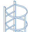
| Cage — distance from the plane of the rungs | from ≥ 650 mm to ≤ 800 mm (point 5.5.1.2, figure 15). | from ≥ 550 mm to ≤ 600 mm (point 7.5.3, figure 7). | The two cages are geometrically incompatible: the ranges do not overlap. A 600 mm deep cage is compliant with 11962 and out of tolerance for 14122-4; a 700 mm one, the opposite. |
| Cage — height of the lowest hoop above the starting area | ≥ 2,200 mm and ≤ 3,000 mm (point 5.5.1.2, figure 14). | ≥ 1,900 mm and ≤ 2,500 mm (point 7.5.3, figure 6). | Overlap zone: 2,200 – 2,500 mm. This is the range to adopt for a single product valid in both fields. |
| Frontal distance from permanent obstructions | In front of the ladder ≥ 650 mm, reduced to 600 mm where obstacles such as pipes or cable trays are crossed (point 4.1.3). | In front of the ladder ≥ 600 mm, reduced to 550 mm at pipes or cable trays (Appendix B, point B.3). | 11962 allows 50 mm less, to account for the tight spaces typical of roofs. Behind the ladder (≥ 200 mm, 150 mm with obstacles) and at the rungs (≥ 75 mm; top rung 60–75 mm) the values coincide. |
| Anti-intrusion device | Normative Annex A, with dimensional requirements and tests: door height ≥ 1,800 mm; free distance between the top of the door and the cage 10–50 mm, with an additional horizontal hatch; on ladders with fall arrest, the top of the device at ≥ 3,000 mm; release control between 600 and 1,800 mm from the walking surface. Tests: 1,500 N horizontal on each corner, 4,500 N vertical on the two bottom corners, a 50 kg spring-loaded body dropped from 2,000 mm onto the hatch. | Required in general terms when it is necessary to prevent access by unauthorised, untrained persons, or those not equipped with PPE; no dimensional requirement and no test (point 7.4.1). | This is a gap in 11962. In the absence of specifications, Annex A of 14122-4 remains the technical reference to adopt and to declare in the documentation. |
From this point on, the analysis covers all the documentation required by 11962.
Table 2 — Documentation required by UNI 11962
| Aspect | UNI EN ISO 14122-4:2016 | UNI 11962:2024 | Design consequence |
| Product designation and rated load | Not provided for: the ladder is a component of the machine and follows the machine’s documentation. | Mandatory (point 5): product + UNI 11962:2024 + class S1/S2 + load in kg. Example from the standard: “Ladder without cage – UNI 11962:2024 – S1 – 150”. | 11962 treats the ladder as a stand-alone product: the designation must appear in the quotation, order confirmation, on the sign, and in the manual. |
| Marking and signage | Permanent marking at the entry and exit points only for systems fitted with a guided fall arrester: manufacturer, year, date of entry into service, reference standards, type of device, PPE obligation (point 7.2). | Marking of every component (symbol or identifying letter + year of manufacture) and a sign always mandatory at the starting or arrival area with manufacturer, year of manufacture, date of entry into service, designation, total height H and flight height h, reference to the manual (points 10.4 and 10.5). For class S1, EN 353-1 marking, type of line and device, reference to the harness, and the PPE obligation are also added. | A significantly broader set of documents, required in every case, not only for ladders with a fall arrester. |
| Inspection and maintenance | Not covered: falls within the machine’s manual and maintenance plan. | Dedicated Chapter 9: inspection before assembly, on use, periodic and extraordinary; maximum interval 1 year for class S1 and 2 years for class S2; table 3 with checks per component (visual / functional / instrumental); repairs reserved to the manufacturer or a person authorised by them; inspection register with a defined minimum content (point 9.5). | This is the most useful difference from a management standpoint: 11962 provides a ready-made inspection plan, reusable as an attachment to the manual. |
| Rescue | Mentioned only as one of the factors in the risk assessment for choosing the device (point 4.2.3, letter e). | Normative Appendix C: the manufacturer must state in the manual the rescue procedures and the additional loads transmitted to the ladder; for class S2 with intermediate platforms, a gate and an anchor point available to the rescuer are mandatory. | To be incorporated both in the instruction manual and in the structural calculation (anchors, stiles, rungs, landings and platforms). |
| Fixing and supporting structure | Only the design loads: ≥ 3 kN on each stile for two-stile ladders, ≥ 6 kN on a single stile, transmitted conventionally to four anchor points (point 5.1.3.4). | Same loads (by reference) plus Informative Appendix D: minimum resistance classes of the supporting structure and type of fixing — timber C24 with screws (not nails), steel S235 with bolts, concrete C20/C25 with mechanical or chemical anchors; masonry and historic buildings assessed case by case by a qualified engineer. Point 10.2: information mandatory at the time of order regarding the installation site. | 11962 governs the interface with the existing structure, which in a machine context is not an issue because the support is the machine itself. |
| Verification methods | Generic list: measurement, visual examination, calculation and/or load test (point 6.1.1). | Table 2: a requirement-by-requirement matrix indicating which method (visual examination / measurement and calculation / test / documentary verification) applies to each point of Chapter 7. | Table 2 is effectively a ready-to-use acceptance checklist, also transferable to work carried out under 14122-4. |
| Legal status and conformity assessment | Harmonised standard under the Machinery Directive 2006/42/EC: the (informative) Annex ZA correlates the standard with essential requirements 1.5.15 and 1.6.2, and warns that the presumption of conformity requires the joint application of EN ISO 14122-1. The ladder is covered by the machine’s CE marking. | Non-harmonised national standard: no presumption of conformity and no CE marking of the ladder product. It stands as good practice and the state of the art for the purposes of Legislative Decree 81/2008. | This changes the documentation logic: the machine’s technical file on one side; the ladder manufacturer’s declaration, manual, marking and sign on the other. |
Operational summary
- Qualify the access before sizing it. Does the ladder primarily serve a fixed machine (or a part of a building whose main function is to provide access to the machine)?
- Yes -> UNI EN ISO 14122-4, together with Parts 1, 2 and 3.
- No -> UNI 11962. The qualification must be put in writing and justified in the risk assessment: the two standards are mutually exclusive.
- Always verify the mandatory minimums of Legislative Decree 81/2008 (in particular Article 113 for fixed ladders over 5 m and with an inclination greater than 75°). The technical standard does not override the legislative requirement: in case of divergence, the mandatory requirement prevails.
- Size according to the values of the relevant standard, paying attention to the six points of genuine divergence: cage depth, height of the first hoop, maximum flight height and total height with cage, spacing of intermediate landings, reference standard for parapets, and frontal distance from obstacles.
- A single product valid in both fields. This is possible for almost all parameters by adopting the most restrictive requirement at every point: first hoop at 2,200–2,500 mm, h ≤ 5 m, H ≤ 20 m with cage, intermediate landings ≤ 5 m, frontal distance ≥ 650 mm, parapets compliant with both 14122-3 and EN 13374 class A. One parameter remains irreconcilable: cage depth, 550–600 mm under 11962 versus 650–800 mm under 14122-4. This is where the field of application must be decided, and two variants produced.
